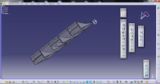
Here is a model I did for the simulation - yellow part is the ground and blue part is the diffuser-like something.
Basic concept: The air travelling under the car gets squeezed, by decreasing area of the channel (diffuser) – it moves with higher velocity causing the drop of pressure.
To understand this concept we need to analyze two most crucial parts of it:
1. Air moves faster through narrow channel.
2. Higher velocity means lower pressure.
2. Higher velocity means lower pressure.
First point seems pretty logical, as it can be referenced by many examples from everyday life. One of them can be water flow in a river. If the river is deep and wide, water travels slowly. If it’s shallow and narrow water rushes through riverbed quickly. Other examples of this phenomenon are e.g.: flow through shower head, various nozzles in water hoses or sprinklers, gas dusters and many more. Physical explanation comes from conservation of mass principle. It says that total mass of an isolated system must remain constant. Let’s think about water flow in pipe. The pipe has a diameter and after a while it decreases. Now let’s take two planes in the first part of the pipe. Water between them has certain volume. If this volume is put in the narrower part of the pipe, the distance between boundary planes must increase – because no mass can be created or vanished. Our volume must travel through both parts in the same time - and since the distance between the planes is greater in the narrow channel it must flow faster (that’s because velocity is displacement during a time interval – and if the time is constant, velocity grows with the growth of displacement).
Flow trajectories through diffuser. Notice the faster (red) flow in narrow part.
Now, the second thesis may seem to interfere with common sense. Let’s think again of a pipe with different profiles. We’ve agreed that water flows faster in narrow channel. That would mean that it has lower pressure in narrow channel also. This can be explained using the law of conservation of energy. It says that total energy (in this case of our fluid volume) is always constant. Total energy of flow is sum of kinetic energy, potential energy, and work. Since potential energy depends on change of height above the ground we can rule it out (assuming that our pipe is on the same level from one end to the other, which is true in this case). That leaves us with kinetic energy and work. Kinetic energy depends on velocity and work depends on pressure. That means if we increase one term, we have to decrease the other to keep the sum constant.
Looking from physical point of view laws governing diffuser work are quite simple. And, in fact, a diffuser is just a pipe, that narrows somewhere near the rear axis of a car generating force that sucks the car to the ground. Of course, if one wants to maximize downforce gain, it gets more complex than that.
Flow trajectories through diffuser. The blue part is the lowest pressure.
Disclaimer:
Explanation is quite simplified, so it’s understandable for someone who is not familiar with the mentioned laws and equations. If you seek for deeper knowledge start from googling “bernoulli’s principle”.
Simulation in this case is not really computing anything, these are just pretty pictures showing the general behavior of air in diffuser, so any numbers are irrelevant (well except maybe for a really small race car ;-)) because of the Reynolds number not being preserved.
Also I decided to make this simulation internal, as it is enough to show the Important things, and saves some time, but one has to be aware that diffuser is actually above the ground.


